

 English
 عربى
عربى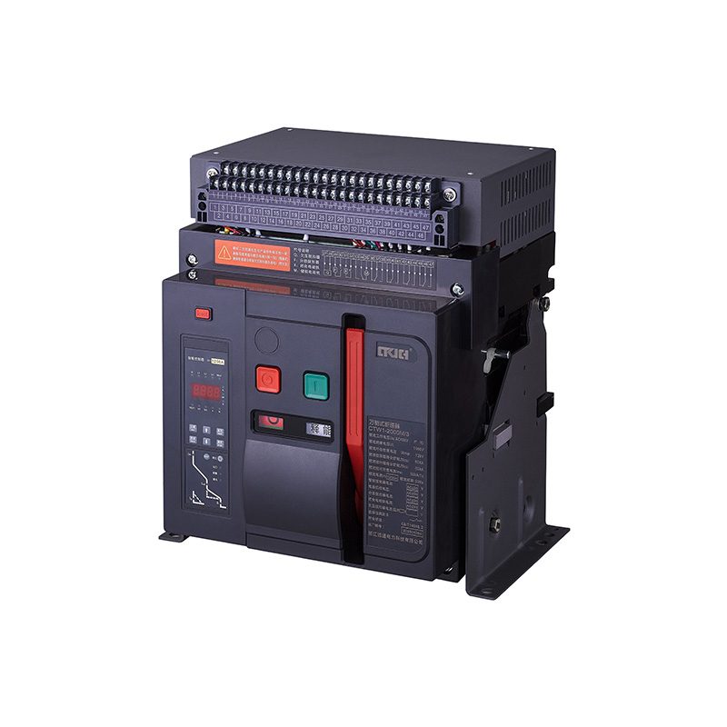
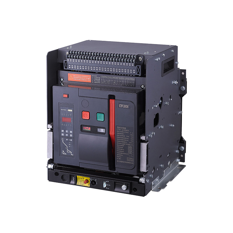
1. High breaking capacity, zero arc distance;
2. Compact contact system, independent small cell, small volume, and reliable working;
3. Reliable interlocking and insulation protection, which makes for better safety;
4. It has fixed type, drawer type, horizontal or vertical wiring, upper and lower inlets, and more choices;
5. Multi different functions intelligent controllers for choosing, with a communication interface, which can realize cluster controls such as remote control, remote adjustment, remote measurement, remote communication, and so on;
6. Intelligent over-current trip protection;
7. Ampere meter, volt meter display function;
8. Its derivative product, photovoltaic grid-connected air circuit breaker, accords with the requirements of a grid-connected circuit breaker, and can be used as the grid-connected switch in the high-power photovoltaic grid-connected switchgear.


CTW1 Series Intelligent Universal Air Circuit Breaker
Model: CTW1-2000
Related Products




Sincere cooperation, welcome to contact us!

Product Categories
Contact Us
 Telephone: +86-577-61801111
 Email: CT@gmail.com
lirongfan1@ctdlkj.cn-
 Company Address
No. 8 Wanhong Road, Zhongfang Intelligent Park, Beibaixiang Town, Yueqing City, Zhejiang Province
Company Address
No. 8 Wanhong Road, Zhongfang Intelligent Park, Beibaixiang Town, Yueqing City, Zhejiang Province
Copyright © by Zhejiang Chengtong Electric Power Technology Co.,Ltd. All Rights Reserved.
